Catalog
-
Catalog
- Agriculture
- Apparel
- Automobiles & Motorcycles
- Beauty & Personal Care
- Business Services
- Chemicals
- Construction & Real Estate
- Consumer Electronics
- Electrical Equipment & Supplies
- Electronic Components & Supplies
- Energy
- Environment
- Excess Inventory
- Fashion Accessories
- Food & Beverage
- Furniture
- Gifts & Crafts
- Hardware
- Health & Medical
- Home & Garden
- Home Appliances
- Lights & Lighting
- Luggage, Bags & Cases
- Machinery, Hardware & Tools
- Measurement & Analysis Instruments
- Mechanical Parts & Fabrication Services
- Minerals & Metallurgy
- Office & School Supplies
- Packaging & Printing
- Rubber & Plastics
- Security & Protection
- Service Equipment
- Shoes & Accessories
- Sports & Entertainment
- Telecommunications
- Textiles & Leather Products
- Timepieces, Jewelry, Eyewear
- Tools
- Toys & Hobbies
- Transportation
Filters
Search
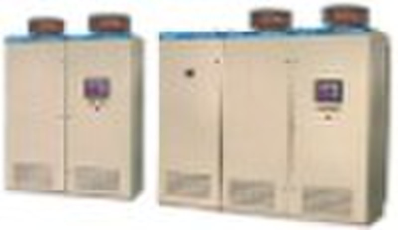
Internal Feedback Chopper Wave Speed Regulating De
original price: 50 000 USD
Shanghai, China
Production capacity:
100 Set / Month
Shanghai, China
086-021-59148555

songqiang huang
Contact person
Basic Information
| Place of Origin | Shanghai China (Mainland) |
|---|---|
| Brand Name | nanzheng |
| Model Number | SN6100 |
| Input Voltage | 690V-10000V |
| Output Voltage | 690V-10000V |
| Output Frequency | 25-60HZ |
| Output Current | 18-980A |
Internal Feedback Chopper Wave Speed Regulating Device: Working principle of internal feedback chopped wave speed regulating device: Please refer to Figure (4) for the internal feedback chopped wave speed regulating scheme. The internal feedback chopped wave speed regulating device is composed of liquid soft-starter, rectifier, chopper and line commutated inverter. Besides, the device is also equipped with a bypass switch and input filter, as well as output filter and capacitance compensation of power factor. The rectifier, chopper and inverter equipped on the internal feedback chopped wave speed regulating device of SN6100 series manufactured by our company are all designed in modular structure, and the chopper and inverter all adopt IGBT elements. Now, we give simple analysis on the speed regulating principle as below.As shown in Figure 4, after being commuted by the rectifier and changed into the pulsating direct current, the rotor current is sent to the chopper by limiting reactor L. The chopper is composed of IGBT elements and a diode as well as capacitor, etc.; wherein, the IGBT mainly operates with actions of periodic conduction and switch off. According to Figure (3), IGBT is switched off during the period of t1. When IGBT is conducted, the rotor current of motor is short circuited by IGBT through limiting reactor L (the reactor is in series with the output terminal of the rectifier), and its loop current rises with the time; at that time, the rotating speed of motor also tends to rise. When the IGBT is switched off, the energy stored in reactor makes the voltage on both ends of IGBT raised and makes the capacitor charged through the diode. Due to the higher impedance at the rear of the chopper, the rotor current will fall with the time and meanwhile the rotating speed of motor also tends to fall. Add a line commutated inverter composed of 6 IGBTs onto the capacitor to increase the energy, make the current changed again into the alternating current and feed it back to the additional winding of the motor stator after filtered by LC filter. When the IGBT is in continuous conduction and switching off, the average value of rotor current is ICP1, which therefore determines that the rotating speed of the motor is N1. When changing the time for switching off of IGBT into t2, the average value of rotor current is up to ICP2 and the rotating speed corresponding to motor is N2. The ratio between the time for IGBT conduction and the periodical time of conduction and switching off are expressed as K, which is called duty ratio; therefore, it is obvious that when changing the duty ratio K of the chopper, the rotating speed of motor can be changed by changing the loop current flow of the chopper. If the chopper IGBT is in continuous conduction, the rotor current will be up to the maximum value (the current is determined by the load moment) and the rotating speed of motor will be the highest value; if the chopper IGBT is in continuous switching off and the rotor current, after being commuted, is completely added onto the inverter and fed back onto the additional winding of the motor; the motor will have the minimum rotating speed (the value of the minimum rotating speed is determined by the data such as rotor winding voltage, feedback voltage and inverting angle of the inverter, etc.); in this way, when, on the one hand, changing the output voltage of the chopper, the rotating speed of motor is also changed, and on the other hand, the slip energy of the motor is fed back to the feedback winding of the motor by the inverter and thus the efficiency of the machine set is improved. Expression of rotating speed of speed regulating system: n = n0 [1- K (U2 / E20 ) cos β min], In the formula, E20 - electromotive force of rotor open circuit (interphase) U2 – feedback winding voltage of motor (interphase) Seeing from the formula, the rotating speed of motor can be changed as long as changing the duty ratio K Basic functions of SN6100 internal feedback chopped wave speed regulating system: the internal feedback chopped wave speed regulating device is composed of liquid soft-starter, rectifier, chopper and line commutated inverter. Besides, the door of the device is equipped with an LCD touch screen with Chinese language.1. "Local/Remote" options for operation The device has the function of "Local/Remote" selective options for operation. User can make a selection as the circumstances. The switch for "Local/Remote" selective options is arranged on the basic window of the touch screen. When the switch is in "Local" position, the ON and OFF of high-voltage breaker, the change between full speed rotating and speed regulating of motor as well as the rotating speed adjustment of motor all can be realized on the touch screen; when the switch is in "Remote" position, the change between full speed rotating and speed regulating of motor as well as the rotating speed adjustment of motor all can be realized through the remote passive contacts (like the output contact of DCS). For the sake of searching and inquiring, when the operator changes the option, the relevant information will be recorded. 2. "Manual/Automatic" options for control The device has the function of "Manual/Automatic" selective options for control. User can make a selection as the circumstances may require. For the sake of searching and inquiring, when the operator changes the option, the relevant information will be recorded. The switch for "Manual/Automatic" selective options is arranged on the basic window of the touch screen. When the switch is in "Manual" position, the rotating speed of motor can be changed by pressing the +/- button to adjust the duty ratio of the chopper; when the switch is in "Automatic" position, the rotating speed of motor can be changed by inputting the current of 4-20mA from outside to adjust the duty ratio of the chopper. 3. Interlocked operation (1) The speed regulating device can be operated on the touch screen of machine cabinet or in the central control room; (2) The ON/OFF of electrically operated gate at outlet and the Start/Stop of the device is in interlocked operation; 4. Automatic-regulation of pressure (or flux) (1) When selecting the operation of device in automatic speed regulation, the device can receive the given revolutions and data of 4-20ma sent by signals of pressure transmitter through DCS system to realize the self speed regulation; (2) When selecting the operation of device in full speed, the rotating speed of motor is rated rotating speed. 5. Bypass operation When the speed regulating device is in failure internally, the device can be automatically converted into full-speed operation and sends out the Local and Remote warning signals; after that, the operation of device can be stopped by manual operation and the motor will work on. In this way, the device can be in maintenance.
Delivery terms and packaging
Packaging Detail: wooden case Delivery Detail: 30-90days
Payment term
Letter of credit
Telegraphic transfer
-
Payment Methods
We accept:


